Collisions with background gas
This feature allows particles to collide with the bacgkround gas through the hard-sphere model. Therefore...
- The background gas is assumed to be of uniform density (constant cross section)
- The working gas (simulated particles) still won't collide with each other
- The background gas isn't affected by the simulated gas
Hard-sphere collision model
The user defines the mean free path between collisions, see below. At every ray-tracing step (create or bounce a particle), MolFlow generates an expected flight path following the Poisson distribution.
- If this expected flight path is larger than the distance of the next wall, no collision occurs
- Otherwise the particle is moved to the expected collision location (a location in the volume), and the collision is executed:
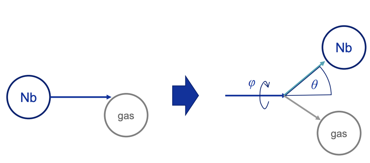
Image: Fabian Manke
There are three physical assumptions:
- Energy is conserved
- Momentum is conserved
- During the collision, forces act along the axis connecting the centerpoints of the two particles
(These three equations are the easiest to write in the frame of reference of the center of mass.)
From the point of view of the test particle...
- Its speed changes
- Its elevation
thetachanges (0=no change, PI/2=turn back) - The azimuth
phiis a random angle (axisymmetric collision)
The result of the equations are:
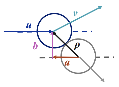
- The impact parameter
b(distance between centerpoint of target particle and velocity vector of simulated particle) follows a linear P.D.F. from0torho, whererhois the sum of the particle radiuses. In other words, hitting the target in its center has the lowest probability, and "sliding off" has the largest.
P(b)=2b/rho^2 - The scattering angle
thetacan be solved from assumptions 2) and 3):
ctg(theta) = 1/2ab * (rho^2 * m_tp/m_bg + b^2 - a^2)
wherem_tpandm_bgare the masses of the simulated and the background gas, respectively. - The new velocity can be derived from the conservation of energy (assumption 1):
v_new^2 = v_old^2 / (1 + (m_tp / m_bg * rho / b * sin(theta))^2
Note
The scattering angle can also be expressed in a different form, with the same result:
b_normalized = b / rho
theta_com = 2 * acos(b_normalized) (theta in center of mass frame)
tan_theta_lab = sin(com_scattering_angle) / (massRatio + cos(com_scattering_angle)) (COM frame to lab frame conversion)
theta_lab = atan(tan_theta_lab)
The post-collision velocity will have a slightly modified form AND slightly different values from version 2.9.28. The full derivation will be posted here.
massRatio = m_tp / m_bg
v_new^2 = v_old^2 * (1 + 2(massRatio/(massRatio+1)^2) * (cos(theta_com)-1))
This new post-collision velocity is verified to obey conservation of mass and momentum.
Usage
To enable the feature, open Tools/Background gas window:
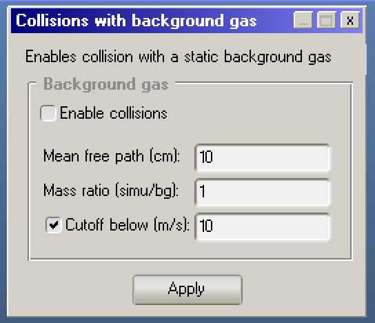
These settings are saved and loaded with the MolFlow file (thus they are a simulation- and not a global parameter)
Parameters
Mean free path (cm)
This determines how often the particles collide with the background
The distance between collisions follows the exponential distribution:
P(d) = lambda * exp(-lambda*d)
where d is the distance until the next collision and lambda=1/MFP is the rate parameter, and its reciprocal MFP is the mean free path.
This also means that at any point during a particle's flight, the distance until the next collision is independent from the particle's history (memoryless property of exponential distribution).
The mean free path can be expressed as:
MFP = 1 / (n * sigma)
where n is the density (1/m3) of the background gas, and sigma is its cross-section (m2)
sigma can be estimated as sigma = PI * (r_simu + r_background)^2 with r_simu and r_background the particle radii.
Links:
Mass ratio (simulated / background)
This determines the new direction and new velocity following a collision
mass_ratio = m_simu / m_background
m_simuis the mass of the "working gas" (i.e. the one that is simulated by the test particles, and whose mass is defined in Global Settings)m_backgroundis the mass of the background gas
For example, if you're tracing N2 molecules (28g/mol), and your background gas is Argon (40g/mol), this parameter is 28/40=0.7
Cutoff velocity (m/s)
If after a collision the simulated particle's speed is below this value, it is eliminated.
If the checkbox is unchecked, there is no elimination regardless of the molecule's speed.
The idea is that very slow particles are likely to be hit by the background gas through Brownian motion and enter a random walk, and even if they drift to a wall, they probably won't adhere to it - in other words, in sputtering terms they become part of the plasma.
Please note that while this option can be enabled, there is no clear evidence at the moment that these slow particles don't eventally end up at a random location. At CERN, we usually disable it.
Visualization and results
Hits display
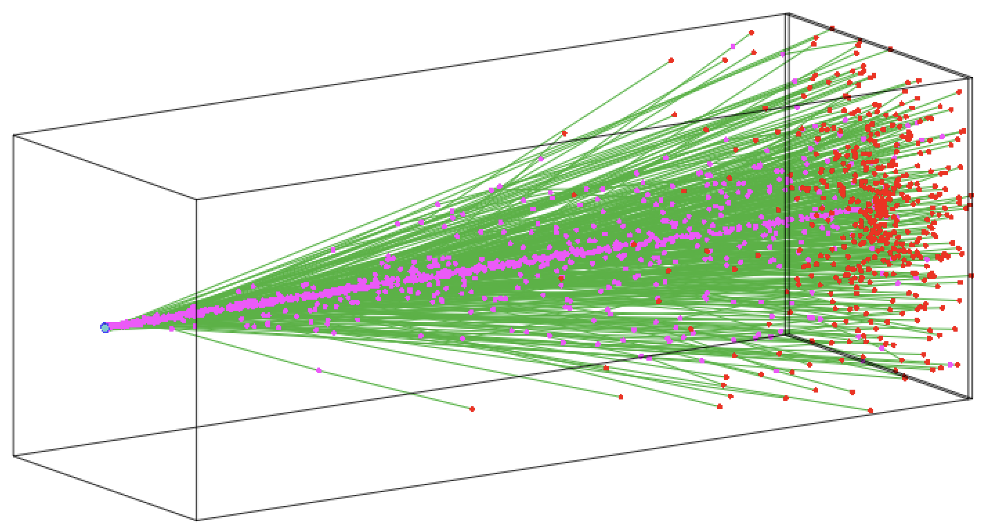
- Purple hits show collision locations
- Red hits (in the volume) show collisions where the new speed is below the cutoff, thus the particle is eliminiated
Formulas
- Volume decays are not counted towards the
SUMABSvariable. In other words, there will be a difference between the total absorptions on all facetsSUMABSand the total created onesSUMDES. (Please note that there is an other difference as well: particles that are still traced: for example a 8-core simulation will have 8 particles that already updated theSUMDEScounter but not yet theSUMABS. This is negligible for large amounts of traced particles.) - The
MFP(mean free path) formula is the average of wall and background collisions. In other words, you'll see that enabling background collisions reducesMFP - The
MPP(mean pumping path) still has the same meaning - average flight path of a particle from creation to elimination. With background collisions on, it can increase since particles fly on a longer path due to collisions, and it can also decrease if partciles get eliminated with "speed cutoff" condition
Speed profiles, and average molecule speed (facet details)
You'll be able to see that speed is affected due to collisions.
First observations
Effect of mass ratio
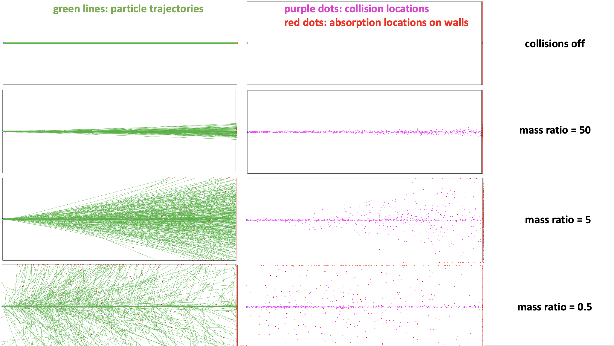
Click for larger view
Larger mass ratio affects the new direction more and more.
Over mass ratio=1, the particles can even turn back.
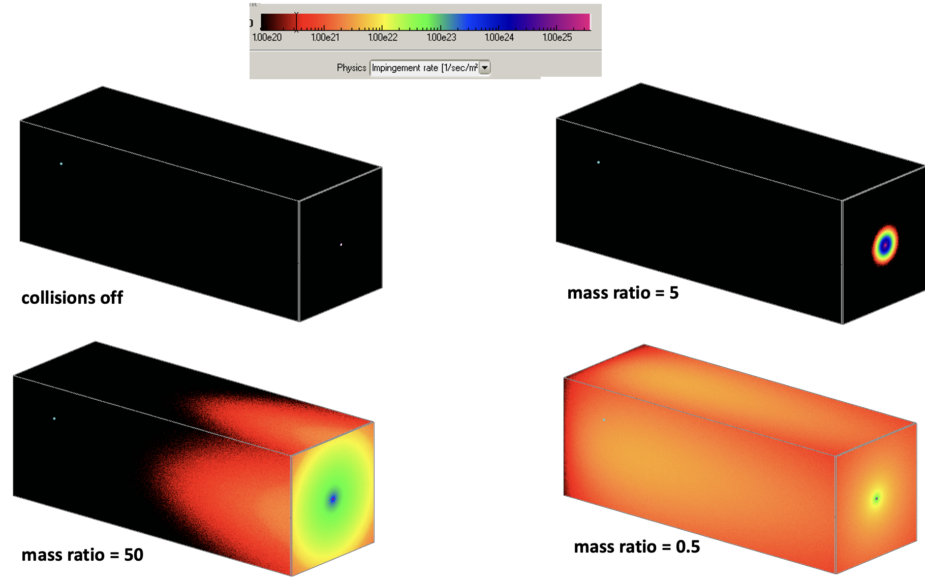
At mass ratio=5, wall collisions more likely towards the end:
- Particles can deviate from jet direction through multiple collisions
- Multiple collisions more likely towards the end (longer total flight path)
At mass ratio = 0.5, wall collisions more likely towards the beginning:
- Particles are lighter than the background, so their direction can change abruptly, even turn back
- Because of this, each point of the jet acts like a new sputtering source
- The jet density is higher in the beginning, as each collision decreases it
- Check this effect in previous image (density of purple points along the jet)
Transmission probability vs. mean free path
We take a L=10cm, R=1cm pipe with entrace and exit at 100% sticking. The transmission probability is defined as the ratio of particles leaving the system through the opposite side exit (instead of returning to the entrance). The measured mean free path is affected by collisions with the wall and with the background gas. In this test, mass ratio is fixed at 1.
![]()
The results are plotted below:
![]()
- Background scattering, as expected, reduces the transmission probability through a pipe
- The system has a “natural”, geometry-based mean free path (In this case 1.81cm)
- When the background scattering’s MFP is lower than that, background scattering dominates
- When background scattering’s MFP is larger than that, wall collisions dominate
Transmission probability vs. mass ratio
![]()
![]()
- When the working gas is very heavy, its direction can’t be changed by the background -> same transmission
- When the working gas is very light, it does a random walk after multiple scatters -> reduced transmission since direct flight path without wall collisions (parallel to pipe axis) becomes impossible
- In-between, transmission probability is gradually reduced as working gas becomes lighter
- As expected, the global mean free path isn’t affected by gas weight